
“As a developer, I want my app to run on Azure”
When tasked as a developer to build a new application or feature, you’ve got a whole bunch of tools in the toolbox to do this in a clean and structured way. Design patterns help you organize code neatly and keep things SOLID & DRY. Patterns like Dependency Injection keeps your classes clean and safe. We group and structure our code into files, folders, namespaces, projects and repositories. We have passionate discussions with other Software Developers about the boundaries of domains and data flows within our systems.
Using neatly organized CI/CD pipelines we take our code, automatically test and verify it as best as we can and then ship it to the cloud. A compute service was set up there for your code to land, most likely by the ops-guy from two offices down the hallway. If you’re lucky, you had the freedom to create it yourself using the ClickOps methodology (Azure Portal), or you dipped your toes into the wonderful world of Infrastructure-as-Code using Bicep or Terraform. When all is set up and running in production, you use monitoring tools to keep an eye on production and make sure everything is running healthy and bugs are fixed as soon as they pop up.
Satisfied after a long day of work you think to yourself: “This is what DevOps is all about!”
At many companies, your responsibility as a Software Developer ends here. The Ops-team takes over and keeps it running and secure, whatever that means. Just let me be clear: I’m not saying this is wrong or a lazy mindset. In fact, it can be extremely empowering for development teams if their cloud environment is managed by a centralized platform team who know all about the best practices. But if you’re anything like me, you’ve often wondered about how deep the rabbit hole goes. And now you’re here: you’ve stumbled upon this blogpost by some random Dutch guy when searching for the next steps in your journey. Hold on tight, and let’s go!
So how does stuff run on Azure?
You probably don’t need me to tell me that The Cloud™️ is just someone else’s computer. In fact, Azure has a whole bunch of computers. Hundreds of thousands of computers across hundreds of data centers in over 60 regions across the world. On those computers it runs layers and layers of software that make it easy for you to create and manage resources via the Azure Resource Manager, the engine underneath tools like the Azure Portal, Azure CLI and also where you send your Bicep and ARM templates to.
Most of these Azure resources are simply some form of an abstraction over the base building block of everything on Azure: a virtual machine. Azure App Services? A relatively thin software layer wrapped around a virtual machine that makes it easy for you to deploy applications to. But you might be surprised that other resources like Application Gateways or Azure Firewall are also “just software” that runs on infrastructure such as VM Scale Sets for enhanced scalability and resilience. They simply expose their management API’s to you as a user in a nicely presented way through the Azure Resource Manager. Ever wondered why certain resources are pretty expensive and billed by the hour? Yep, you guessed it: it’s running on a virtual machine.
Serverless offerings such as Azure Functions take this a step further to add additional layers of abstraction to spin up tiny containers that are measured and billed by the seconds of execution time. And at the very end of the spectrum of IaaS -> PaaS -> … is SaaS, which is hosted software running on a combination of these infrastructure and platform resources.
Behind the scenes, Azure achieves all this by running workloads on shared hardware, isolated at the hypervisor level where virtual machines are created. Network traffic is routed to and from these machines using Software Defined Networking, which has robust traffic controllers in place to make sure no traffic gets sent to the wrong place. On top of these layers of infrastructure abstraction, you can define your own virtual networks to manually control the way network traffic flows between all resources that you need.
VNets & Subnets
Now that we’ve got a feeling for the infrastructure that powers Azure behind the scenes, we can take a look at how custom virtual networks work, and how you can utilize them for your own systems.
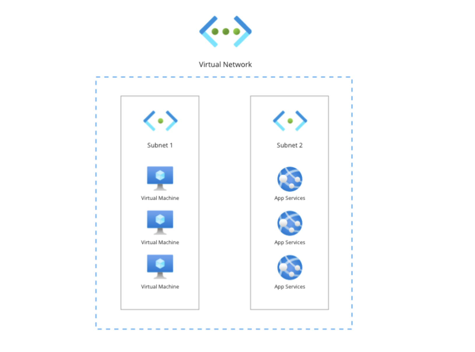
A VNet or Virtual Network is the central building block for building your own networks. The simplest explanation is that it’s a boundary around resources with a certain size. To organize your VNet, you can create subnets. These are a tool to help you further structure and group your resources within the VNet. For this section I’ll show you how to build a VNet structured like the diagram below. The goal of this VNet is to contain some workloads that are running on virtual machines and App Services. To organize this VNet, we’ll create two subnets where we’ll place the individual resources needed.
The size of a VNet is based on how many IP addresses are inside of the VNet. When creating your first VNet, you’ll be asked for a network size in Classless Inter-Domain Routing (CIDR) notation like: 10.0.0.0/16. CIDR is a useful tool to easily segment a network into smaller pieces.
The difference between an IP address and a CIDR block is best explained like this: in the digital city called Azure, an IP address points to an individual house, but a CIDR block refers to the street, suburb or even bigger.
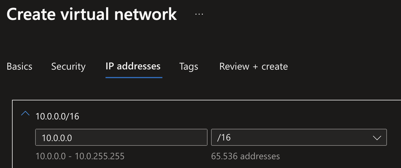
In this example, the /16 (called the IP network prefix) refers to first 16 bits of the IP address (which has 32), so it really means: Any IP address between 10.0.0.0 and 10.0.255.255. So if you’re going to create a VNet with size 10.0.0.0/16, what you’re actually saying is you want to reserve 65,536 IP addresses starting from 10.0.0.0. When creating a new VNet in Azure Portal, it shows you a nice overview of how many IP addresses are actually going to be reserved for you to assign to resources:
Though, 65,536 IP addresses is pretty large range of IP addresses! In the case of the diagram shown above this would be overkill. It’s good to keep some space in your VNet, but you’ll want to think about what resources you want to place inside of the VNet and how many IP addresses they need. This is called creating an IP plan, and you’ve got to think about reserving the right ranges from the very start, because as you’ll later see, you can not connect VNets together if they have any overlap in IP ranges in them.
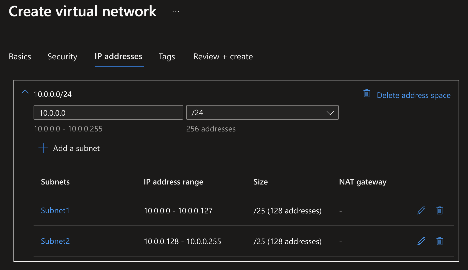
Imagine the situation shown earlier: a VNet with a bunch of VM’s and App Services. The company might be growing their customer base every year and will require regularly adding new instances to handle the load, but it’s definitely not going to go past a few dozen instances in the next couple of years. So reserving an IP block like 10.0.0.0/24 would be safe: reserving 256 IP addresses between 10.0.0.0 and 10.0.0.255.
To further organize this VNet and group the same type of resources together, you’d want to place them into a subnet. Subnets also require you to reserve an IP block for them within the VNet, and in this case I want to split them 50/50. During subnet creation, you’d define this range by simply defining a CIDR range with a smaller IP network prefix. So creating Subnet1 with range 10.0.0.0/25 and Subnet2 with range 10.0.0.128/25 would result in the creation of two subnets with the reserved address space of 10.0.0.0-10.0.0.127 and 10.0.0.128-10.0.0.255.
Why is the
10.0.0.0/8range used for all these Azure networking samples? That’s because this range is part of the RFC 1918 Spec for Address Allocation for Private Internets. In this spec, multiple IP blocks are reserved for networking in private internets. These IP addresses are not publicly available to host websites on, thus are safe to use for internal networking.
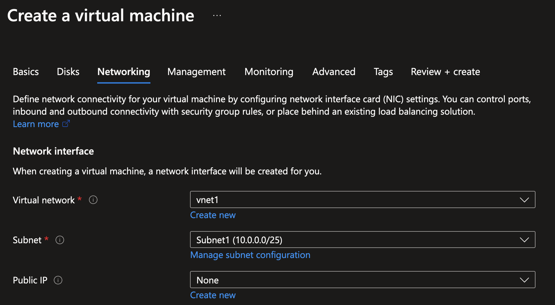
When you’ve created your first VNet, it’s easy to deploy new resources into them like shown below for a new virtual machine. In this example we’re just going to be asking for a private IP address for this VM by placing it in Subnet1, as generally it’s bad (and unsafe) practice to assign a public IP address to a VM without proper security measures in place.
After the virtual machine has been created, you can inspect what IP address was assigned in the Azure Portal.
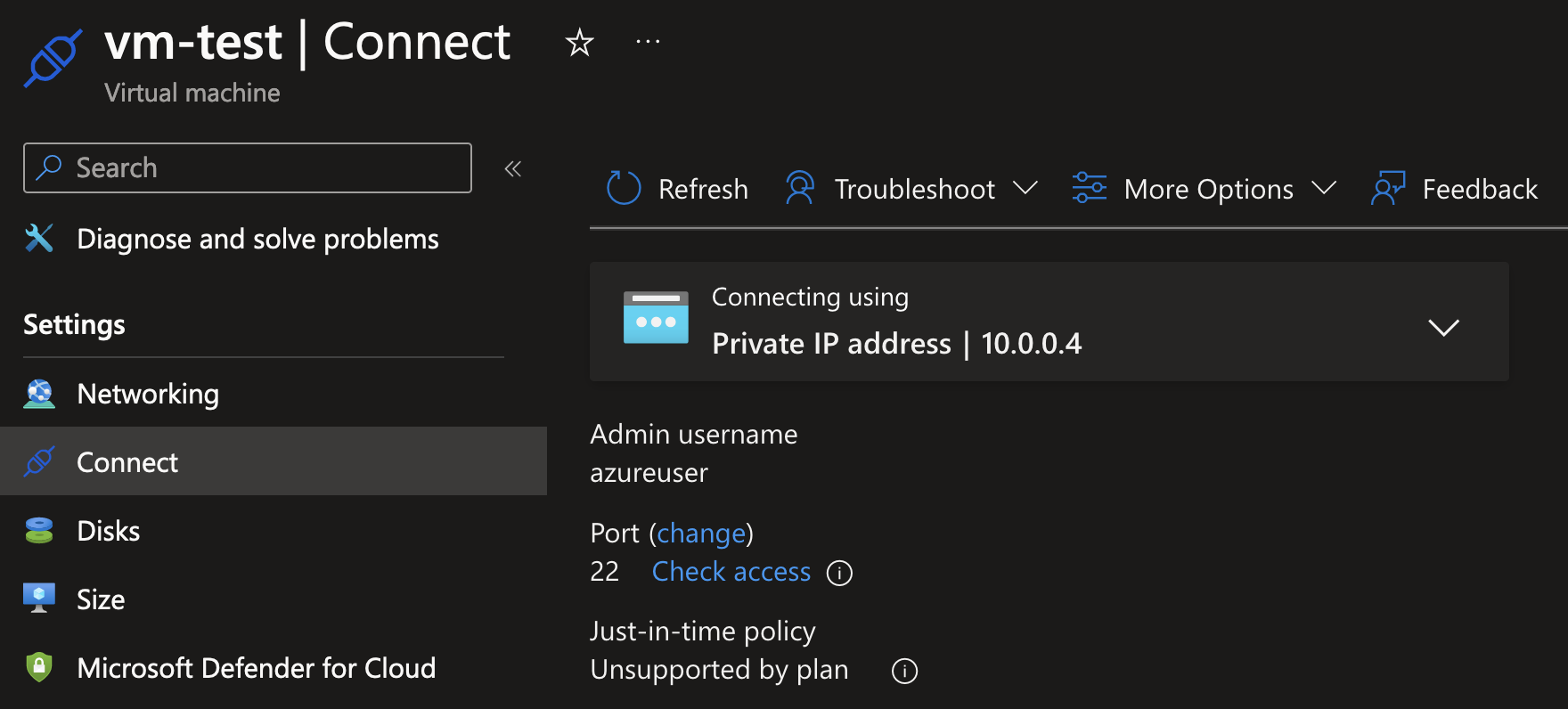
You can also easily move most existing services into VNets, most often via the Networking menu item in the resource blade sidebar. In this case, I’ve configured an App Service to be assigned to Subnet2.
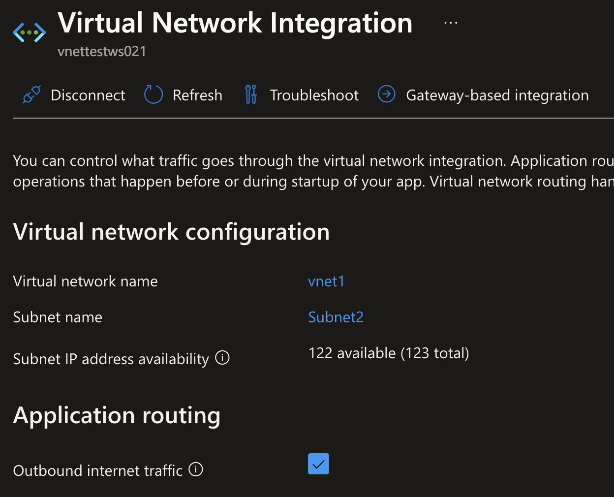
Depending on the resource it’s going to assign a static IP address, or do this dynamically. A basic virtual machine will get a static IP address within your subnet, but more dynamic compute resources like App Services, Functions or Container Apps could be assigned IP’s at random while scaling up and down.
Now that we’ve got the private IP address for this virtual machine, we can try and ping it from the App Service which is also integrated with the VNet!
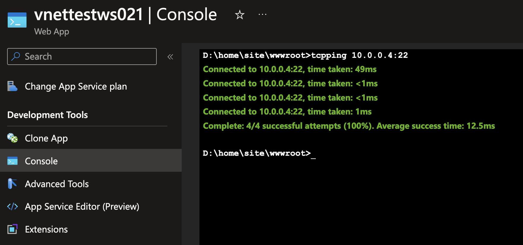
Great! In these few steps, we’ve created a new Virtual Network and placed both a virtual machine and an App Service inside of a subnet.
TL;DR: VNets & Subnets
- VNets are network boundaries for resources, with a size determined by a CIDR IP block.
- VNets can be further divided into subnets, which require a subset of the VNet IP range.
- Resources placed in any subnet can get an IP address from the reserved subnet IP range.
- Resources can have both a private and public IP address when running in a VNet. Placing resources in a VNet does not automatically make them unreachable from the internet without further configuration.
- By default, all resources in VNets can automatically connect to each other, even if they are in different subnets.
- Creating and managing VNets is totally free, but there might be resource-specific costs attached for deploying them in a VNet. Be sure to check out the SKU comparison page for your desired resources, and run them through the Azure pricing calculator.
Connecting VNets using Peering
Now that you know the basics of VNets, it’s time to take the next steps. Because in practice, you’re not going to run one big VNet with every single resource inside of them, as by default, every resources inside of a VNet can reach any other resource. Not very practical and secure if you want to host a couple of different workloads such as a couple of virtual machines for hosting business-critical applications next to an Azure Virtual Desktop environment for employees. Those employees should probably not be able to connect to these VM’s without any additional security controls in place!
For this purpose, you can create multiple VNets with each their own purpose. For example, a VNet for Application VM’s, a VNet for SQL Server, a VNet for Remote Desktop machines and more. Or perhaps you want to keep it simple but at least separate the Test, Acceptance and Production environments into separate VNets.
But then you run into the following issue: you want to keep things separate, but still allow some form of connectivity between VNets. For that, you can Peer existing VNets together. Let’s take a look at what that looks like.
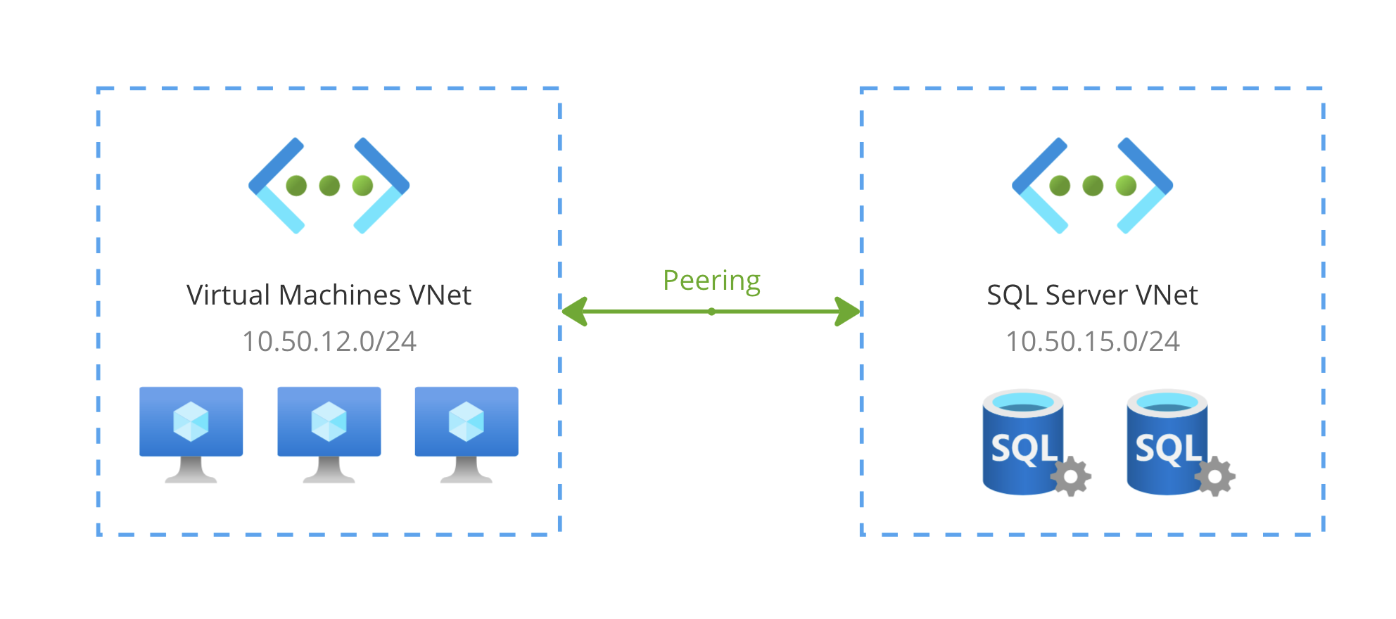
The resulting network of the diagram shown above is one that contains IP address ranges 10.50.12.0/24 as well as 10.50.15.0/24. Resources in both VNets can freely communicate with each other as if they were located in the same VNet. They’re basically “stitched” together. On a technical level, any communication between these VNets goes through the Azure backbone network, enabling high-speed communication and minimal latency while being private-only.
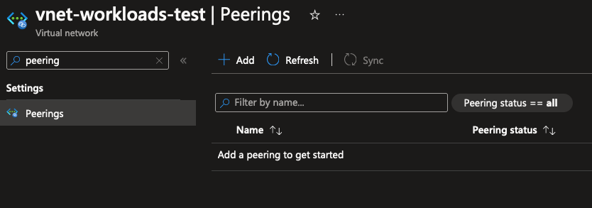
In Azure portal, you can go to the peerings menu item to manage and create new peerings:
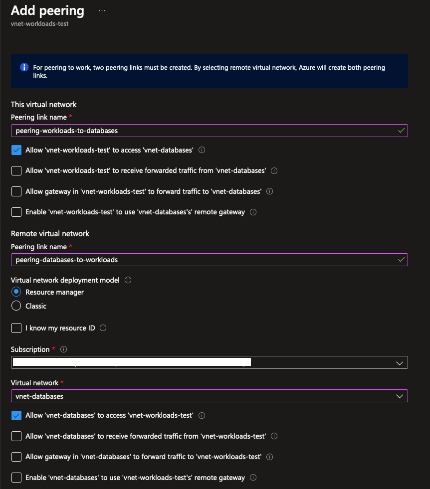
From there, you can create a new peering connection. As you can see in the screenshot below, you’ll need to set up a peering from both VNets to complete the connection. You can configure the behavior here for either side of the peering connection:
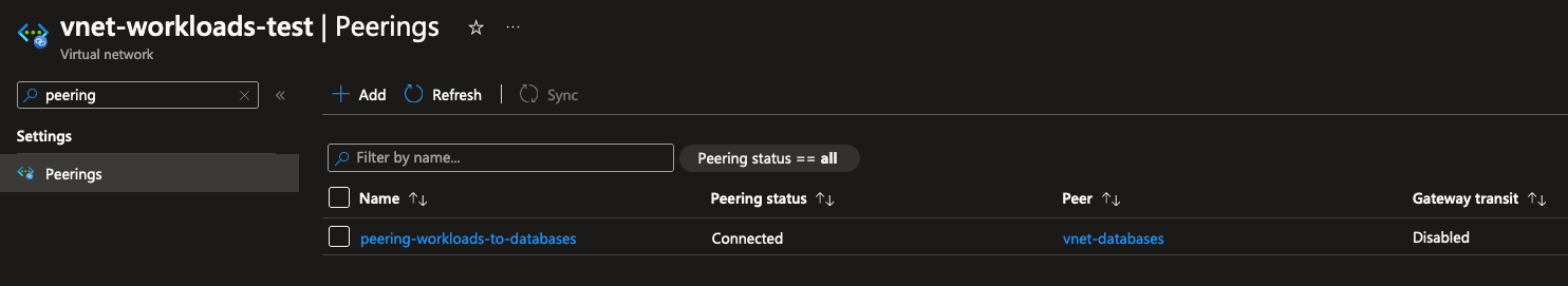
After creating the peering, you can view the status on the peering overview page:
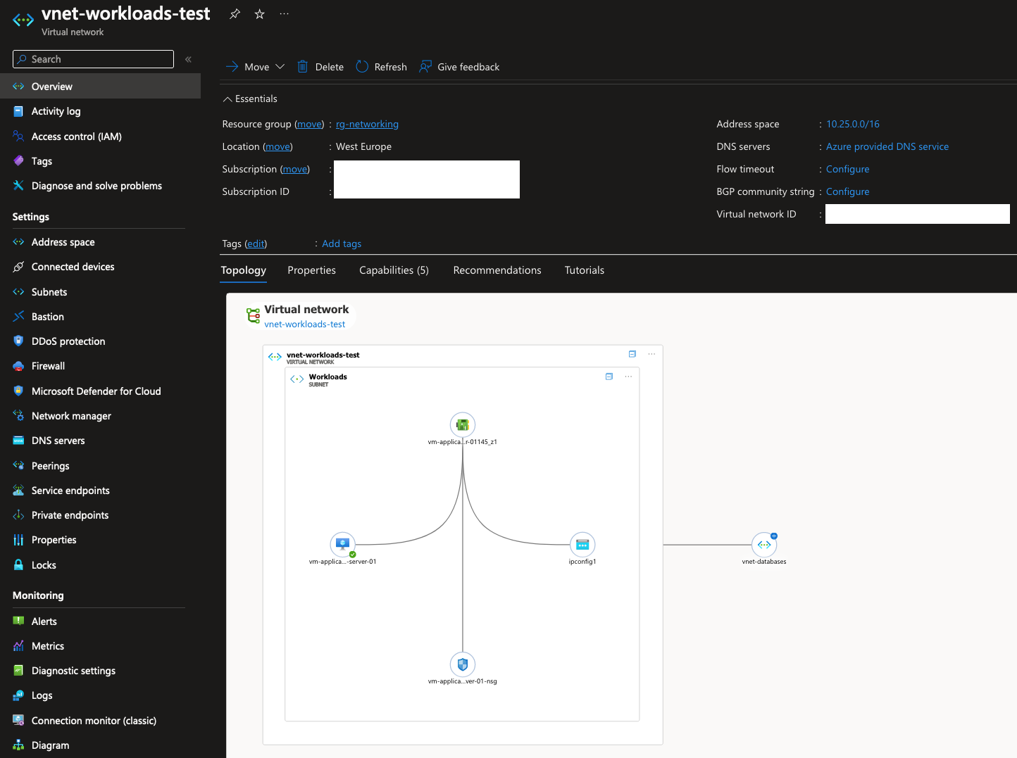
A nice added feature is being able to view the network topology of your VNets on the resource overview page. There’s a more detailed view available too, which allows you to filter/search further and inspect topologies spanning multiple regions in Azure.
Now, imagine a bigger network, like a network with a central Firewall enabling secure public-facing connectivity for both a Test and Production environment. The production environment could have a more elaborate set-up, like having a dedicated VNet for hosting a pool of SQL databases.
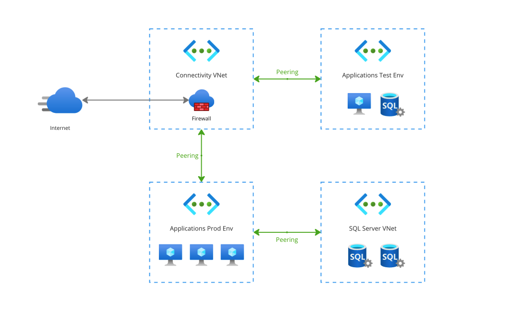
Based on what I wrote earlier about stitching networks together, you would instinctively think that this a less-than-ideal set-up: if the test environment is connected to the same connectivity VNet as a production environment, can’t you reach the production SQL databases from the test environment?
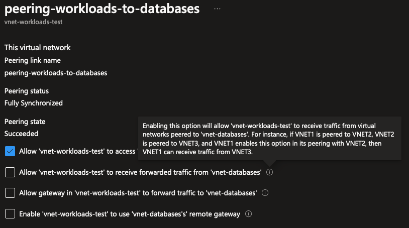
The answer is actually no! While it’s true that VNet Peering causes networks to be stitched together, it does not mean that if you plug anything into an existing web of networks, that every part of that network can automatically reach any resource in any VNet. This is because for each peering, you have to configure behaviors like this explicitly. In this case, if you would want a VNet to be able to connect to another VNet through a shared connected VNet, you would have to enable “Allow … to receive forwarded traffic.” like seen below:
There’s so much more to write about VNets and peering, like how VNets are always region-bound but peering between VNets can be done across regions on a global scale. Or how Private Endpoints can be deployed in your VNets to allow private connectivity between compute resources and Azure services like Azure SQL or API Management. But I’ll leave those for a future blog, as this blog is just an introduction to all things networking!
TL;DR: VNet Peering
- Peering two VNets together effectively “stitches” the network ranges into one big super VNet, with network traffic being able to freely flow between them.
- VNets cannot be peered together if there’s any overlap in IP ranges. Always plan out your VNets according to current and future requirements, and make sure to assign them all unique IP ranges.
- Peering many VNets together does not create a big network with 100% free flowing traffic: each peering has to be explicitly configured to allow forwarded traffic to a VNet.
- There is a nominal cost charge attached to peering VNets together: a couple cents per Gigabyte of traffic over a peering connection. Check the Azure pricing calculator for more details.
Protecting subnets using NSG’s
Now that we’re got our VNets set up and peered to each other, don’t we have one super-VNet where all resources running inside of them can connect with any other resource in the network? Well yes, that’s true. VNets and Subnets are just a way to segment and divide your networks, and peering is just another tool in the toolbox to expand your network.
Of course, in practice when you’re building applications, you’re already going to come up with security solutions such as not using the same database login credentials for applications or using Managed Identities to make sure only the correct applications can connect with their own database. But as a part of layered security practices, it’s also good to tackle this on the network level. To truly control how traffic flows within your network, you can use Network Security Groups (NSG’s).
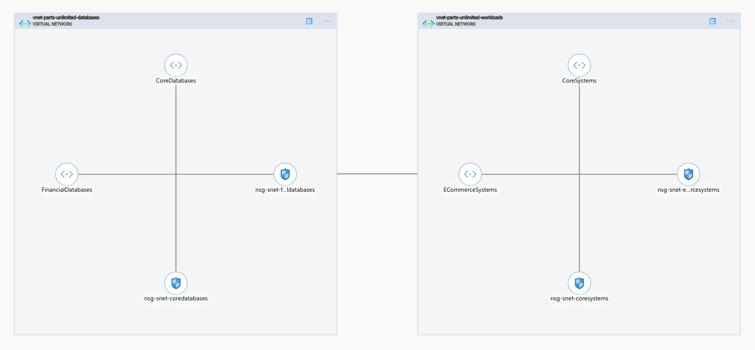
For this section, imagine the following network topology:
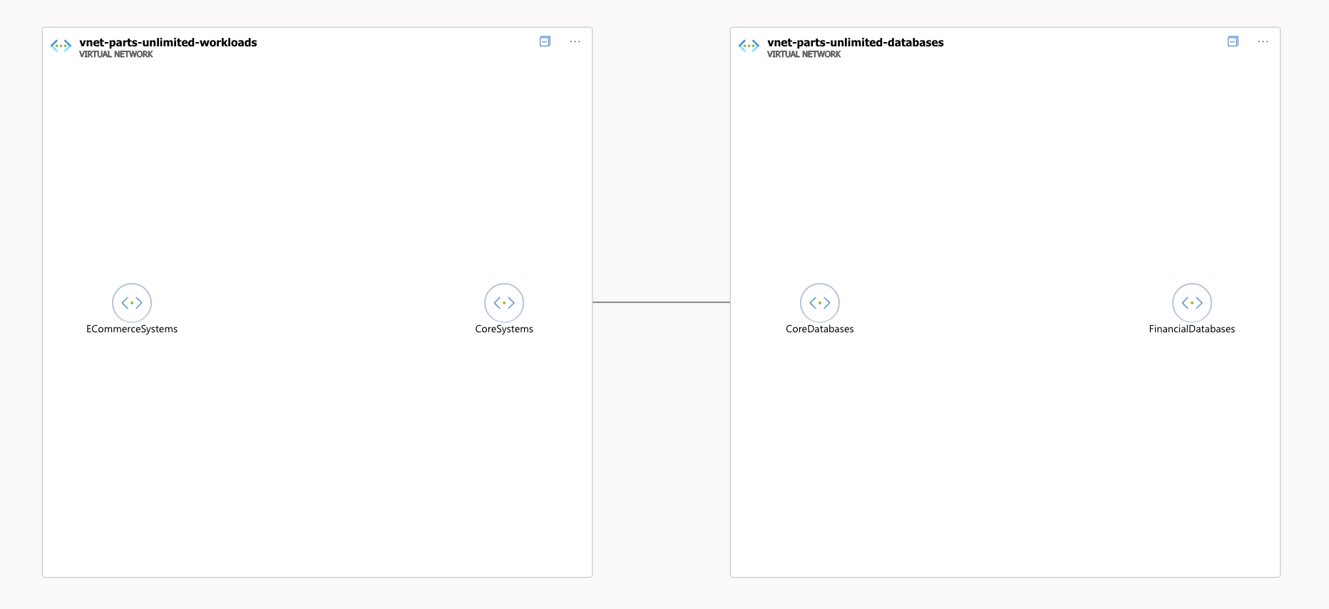
The ECommerceSystems subnet will contain workloads for hosting different webshops and processing payments. Those systems will interact with the systems hosted in the CoreSystems subnet for processing those orders and handling all things ERP-related. Those Core systems should be able to reach the databases in the CoreDatabases subnet. But only a tiny part of those Core systems should be able to write data to the databases in the FinancialDatabases subnet: only the order flow system within the Core systems subnet. In any case, the E-Commerce related workloads should not be able to query databases directly without going through the Core systems API’s.
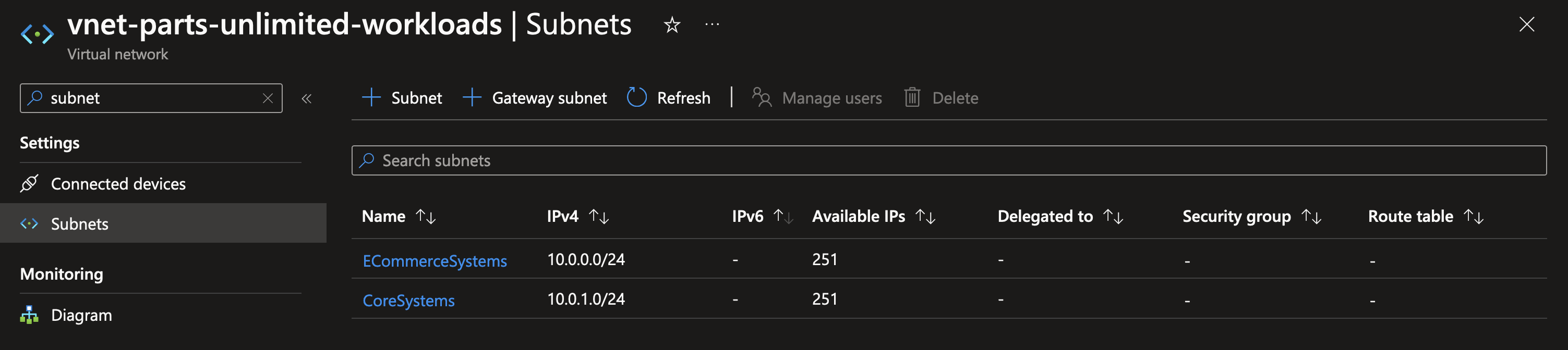
When viewing your VNet in the Azure Portal and navigating to the subnets inside of it, there’s no route tables and security groups created for these subnets by default. This means that traffic between these subnets can flow freely without any restrictions, which means the requirements drafted above are not met. Because both VNets are peered together and neither contain any security groups or route tables, this means that traffic also flows freely between the workloads and databases.
To start protecting subnets, you can create a new Network Security Group via the resource manager. After you’ve created one, you can view the default configuration which shows you what the use and potential for an NSG is.
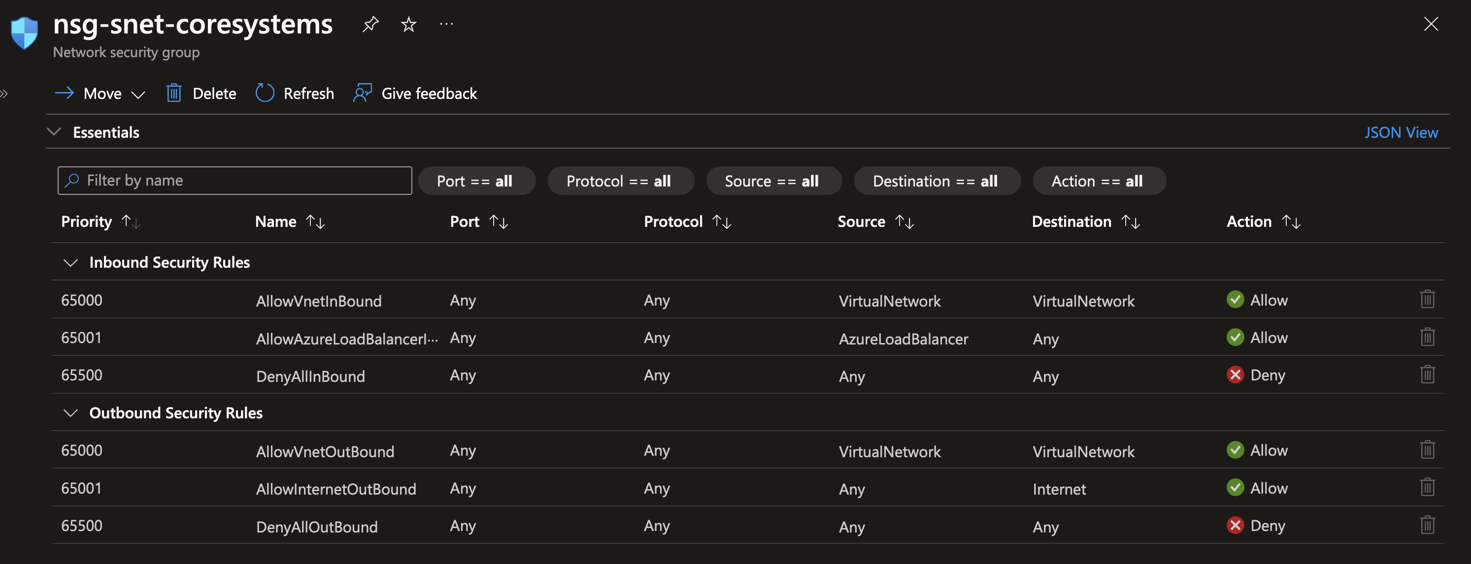
In short: a NSG is a virtual firewall on the subnet level. You can define rules in an NSG that allow or deny inbound and outbound traffic based on the following parameters: protocol, source IP address range, source port range, destination IP address range and destination port range. Using these, you can control very specifically who is allowed to connect with resources within the subnet, and who is not. Additionally, you can use NSG’s to control which traffic is allowed to traverse outside of the subnet using outbound traffic rules. Each subnet can have only one NSG connected, but a NSG can be connected to multiple subnets to allow for reuse of configuration.
By default, a NSG contains the following set of rules:
- Inbound: allow all traffic from other VNets
- Inbound: allow all traffic from Azure Load Balancer
- Inbound: deny everything else
- Outbound: allow all traffic towards other VNets
- Outbound: allow all traffic to the internet
- Outbound: deny everything else
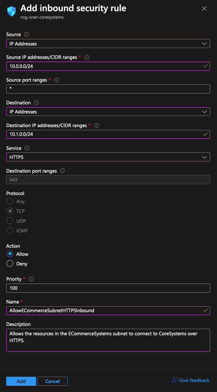
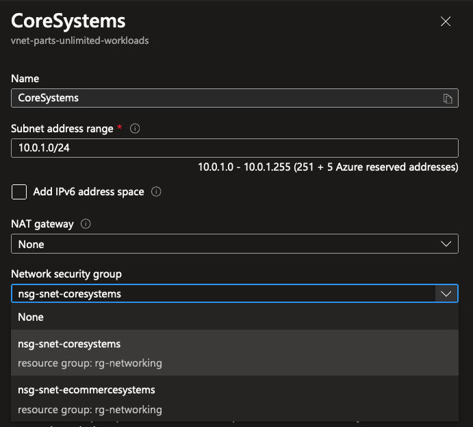
The default configuration does not yet cover our requirements for protecting the subnets, but it’s really easy to set up a new rule in a NSG. Let’s first set up a rule to strictly allow the ECommerceSystems subnet to connect to resources in the CoreSystems subnet over HTTPS:
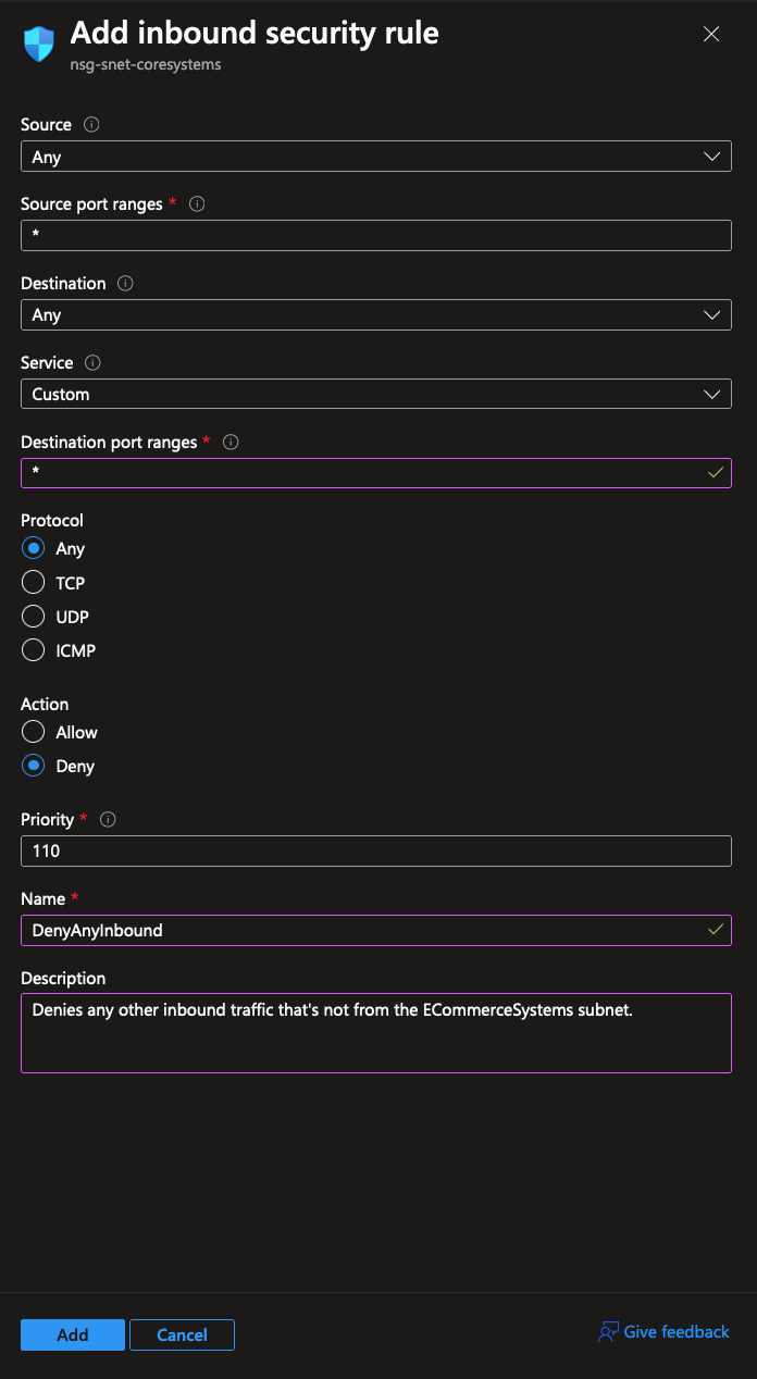
The default behavior of a NSG is to allow all inbound traffic from other connected VNets and subnets. That’s why we have to explicitly set up a deny rule for any other form of inbound traffic:
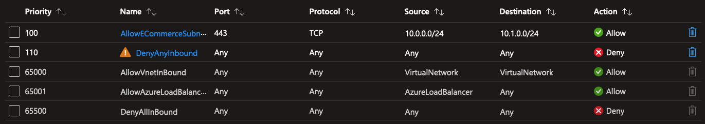
The result is the following: an explicit allow rule for the ECommerceSystems subnet, and an explicit deny rule for any other kind of inbound traffic.
Note: the warning icon in the screenshot is shown because the
AllowAzureLoadBalancerrule is overridden and blocked. In a real production scenario, you should be careful to tweak these settings specific to your needs.
Now that the NSG is set up and configured, it’s easy to attach to a subnet by modifying the subnet settings:
The results speak for itself, well, at least somewhat. The network topology diagram in Azure Portal isn’t always the clearest in visualizing these things. But now that we’ve attached a NSG to every subnet in the network, we can start implementing all network traffic requirements using these NSG’s.
This is what NSG’s are about in a nutshell: deciding which traffic is allowed and denied to move in-between subnets. A mini-firewall if you will.
There’s much more you can do with NSG’s, such as using Service Tags to easily allow Azure services to connect with resources without managing IP ranges. Next to NSG’s, there’s also Application Security Groups: these are meant to group virtual machines together and allow for similar functionality to NSG’s without having to manage lots of IP addresses in rulesets.
TL;DR: NSG’s
- Network Security Groups (NSG’s) are virtual firewalls on the subnet level, allowing or denying traffic through the use of rules.
- A subnet can only have one attached NSG.
- NSG’s can be attached to multiple subnets at once to share the configuration.
- It is free to create and manage NSG’s. There is no cost attached to evaluating NSG rules.
- It is best practice to always attach a NSG to a subnet, even if you’re not planning to implement them further right now.
Building a Hub-Spoke topology using UDR’s
Now let’s dream up another scenario to introduce the last part of fundamental Azure networking infrastructure. At the company you’re working for, you need to run workloads behind a firewall. The firewall has two uses: it protects workloads from unauthorized access coming outside of your network. At the same time, it also prevents you from connecting to systems outside of your network without setting up explicit allow rules to do so. Generally speaking, the recommended best practice for hosting a firewall is to use a Hub-Spoke network topology.
The concept of this topology is to utilize a hub VNet that contains shared networking infrastructure that should be used by all of the spokes, which can be VNets like your T/A/P environments, an Azure Virtual Desktop environment or any other workload you want to protect. Because the shared networking infrastructure is in one place, it’s cost effective and easy to maintain centrally. Different spoke workloads can then be plugged into the hub without needing to set up their own firewall or other network appliances.
In a simplified diagram, a Hub-Spoke network topology can look like this:
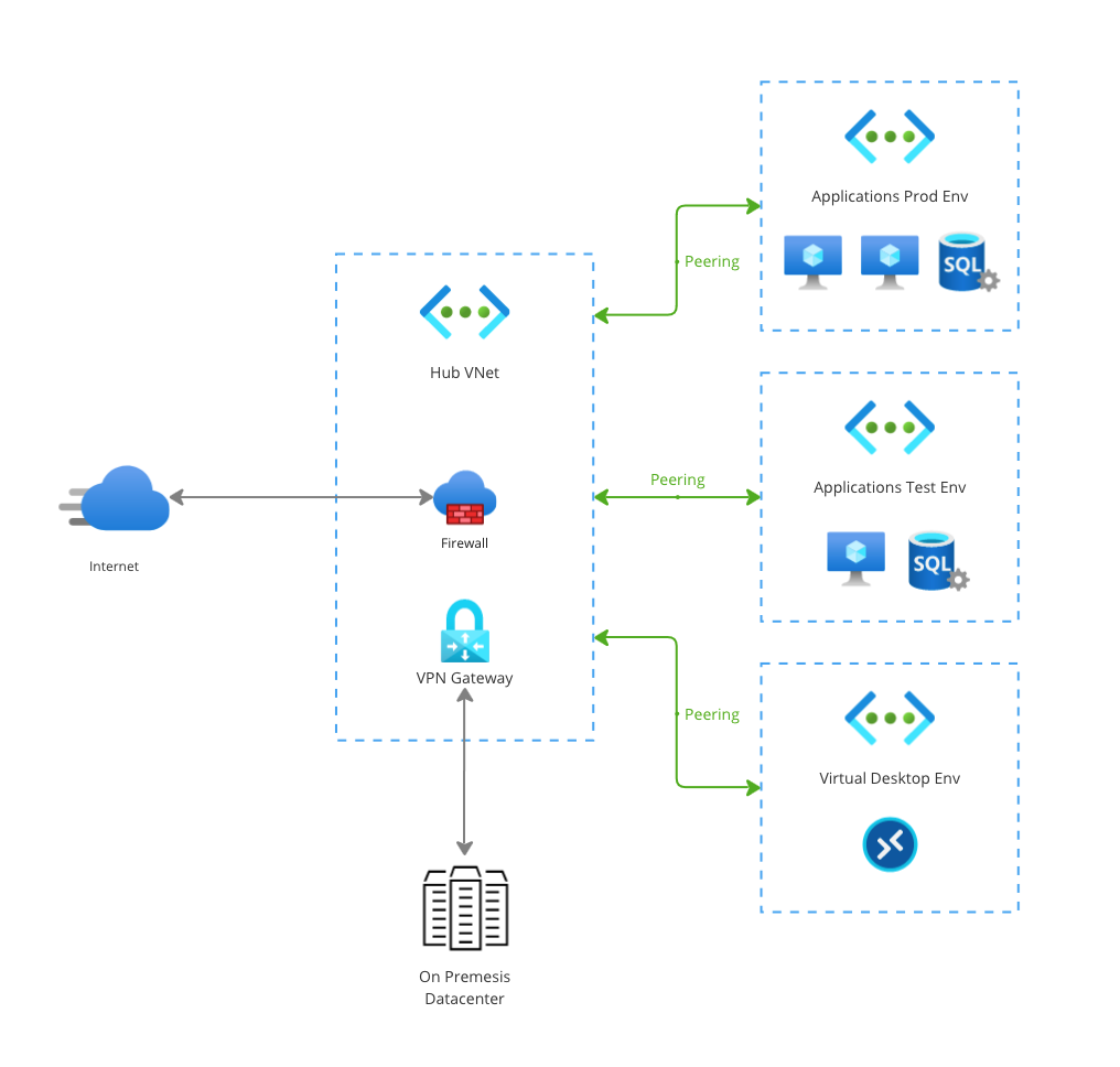
All the spokes contain different workloads with different purposes. They all use VNet peering to connect to the hub VNet, where two central appliances are hosted: a firewall and a VPN gateway to allow for on premises connectivity. This set-up is simple yet extremely powerful, because every single spoke can easily reuse these connectivity features without having to deploy these resources multiple times which can easily cause a significant bill.
For this fundamentals blog, there’s one last component missing to make this set-up happen: the ability to direct network traffic to the right place. Because by default, VNet peering just stitches networks together. It doesn’t automagically redirect all traffic on the network through a firewall to the internet.
In Azure, you can achieve this using User Defined Routes (UDR’s).
Routes are stored in a route table, which look a bit like this:
| Address Prefix | Next Hop Type |
|---|---|
0.0.0.0/0 |
Internet |
10.0.0.0/8 |
None |
They contain an address prefix IP range, and a next hop type. When traffic leaves a subnet, it points toward a specific IP address. These can be caught in a route using the address prefix. The next hop type can then be used to determine where to point the traffic towards: should it point to the internet, perhaps a network virtual appliance or a virtual network gateway?
By default, when you create a subnet to host resources in, a bunch of system routes are assigned by default to direct where traffic goes when leaving the subnet. These are not visible or configurable in the Azure Portal, but you can override them later with your own User Defined Routes. It’s good to take note of the following default routes:
0.0.0.0/0 -> Internet: the0.0.0.0/0range is shorthand for any IP address on the internet. It’s next hop type is set let traffic flow onto the internet. The default behavior of this system route is to route egress traffic through a random IP owned by Azure. Additionally, Azure is able to detect whether target IP addresses belong to Azure, and in that case it will route all traffic through the Azure private backbone.10.0.0.0/8 -> None: reserved for private networking per the RFC 1918 spec. This route makes sure that traffic on the10.0.0.0/8range doesn’t go anywhere unless you peer networks together or create your own routes.
You can read more about all default routes and their use cases here in the docs.
Now, to enable our Hub-Spoke topology to work well, we’re going to need to override the system default routes with our own User Defined Route. This will allow us to direct traffic that’s headed outbound for the internet through an Azure Firewall, which can then make the decision whether it’s OK to pass through or should be denied.
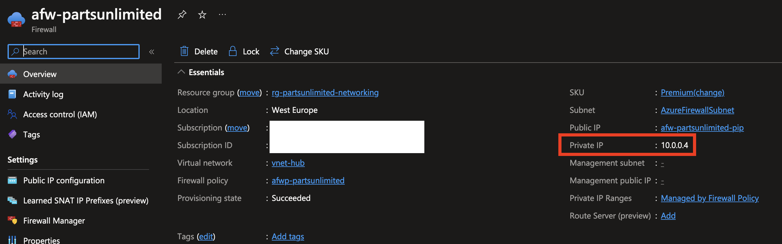
To start, let’s deploy a firewall so we have a place to route traffic through. It requires that the subnet to deploy to is called AzureFirewallSubnet. You’ll also need to assign a public IP address to the firewall: this is IP address that can be used to connect to the workload resources through Azure Firewall, but it’s also the public IP address where traffic from your private network is egressed from, which can in turn be used by third parties to whitelist traffic coming from your network.
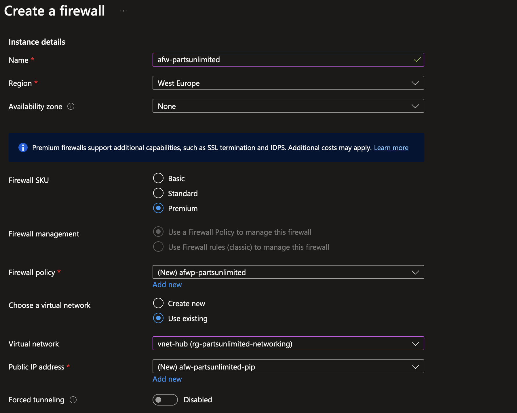
Note: be very careful to delete/shut down Azure Firewall when experimenting. The standard and premium SKU’s are extremely pricey.
The resulting Azure Firewall instance gets assigned a private IP address, in this case 10.0.0.4. This is the IP address that our traffic can be routed to using UDR’s!
As the peering connection is already created between the hub and the spokes, it’s simply a matter of creating a new route table and assigning it to the subnet where you want to change the routing for. Using the Azure Portal, I deployed a new empty route table resource for the test environment workloads subnet.
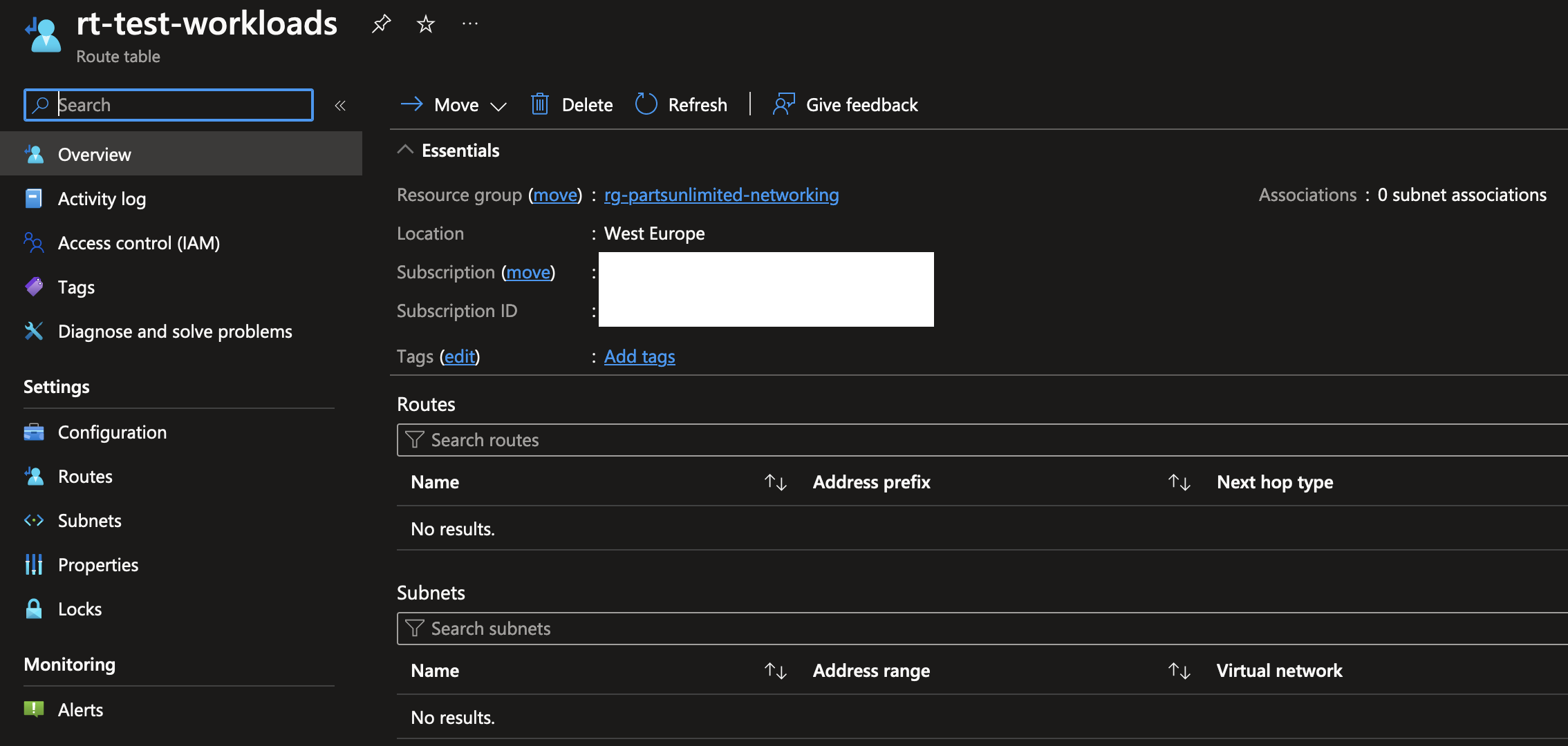
To start off, in the subnets menu, you’ll need to associate the route table with an existing subnet. You can also do this via the subnets menu when viewing a VNet, just like we did earlier when creating a NSG.
Next, in the routes menu within the route table, create a new route. There’s a couple of options you can fill in here. To redirect all traffic pointing to the internet, you can again use the IP range of 0.0.0.0/0. For the next hop type, you should pick “Virtual appliance” for Network Virtual Appliances (NVA’s) like firewalls. The final option is the next hop address, which should point to the private IP address of the Azure Firewall instance deployed in the hub network.
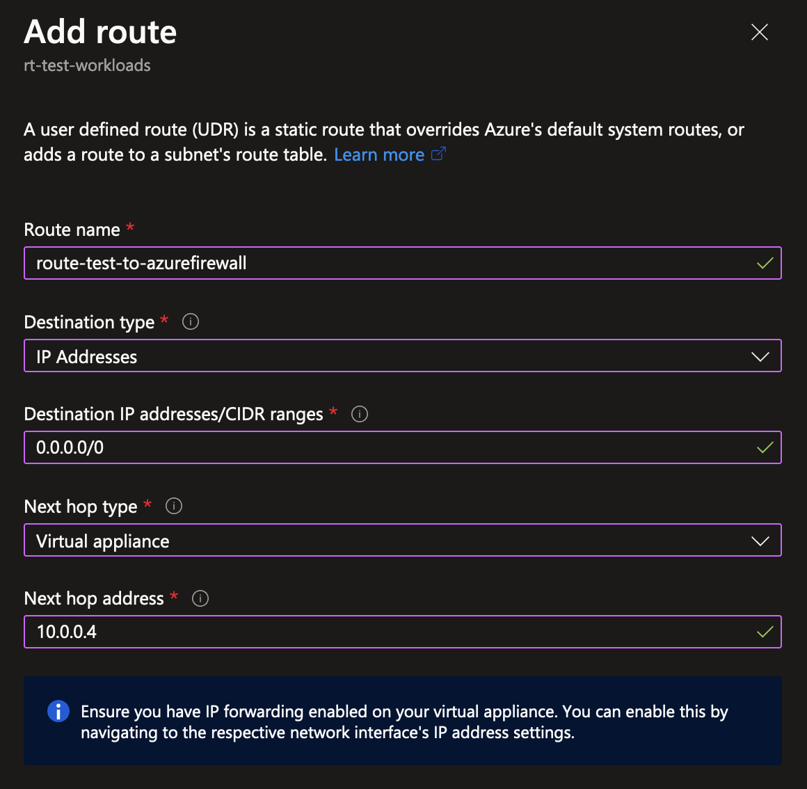
That’s basically it! As mentioned earlier, the default system route table contained a route to point 0.0.0.0/0 to the internet directly. Now instead, any and all traffic pointing towards the internet instead gets redirected to the Azure Firewall instance.
For demonstration purposes I’ve deployed a virtual machine in the test environment spoke network. It has no public IP address, and is deployed in the subnet where the route table is set up and configured. As you can see in the Azure Firewall logs, after deploying the VM it immediately starts building some connectivity with outside sources. Because the default behavior of Azure Firewall is to block everything unless explicitly allowed, you can see the action is “Deny” for all traffic.
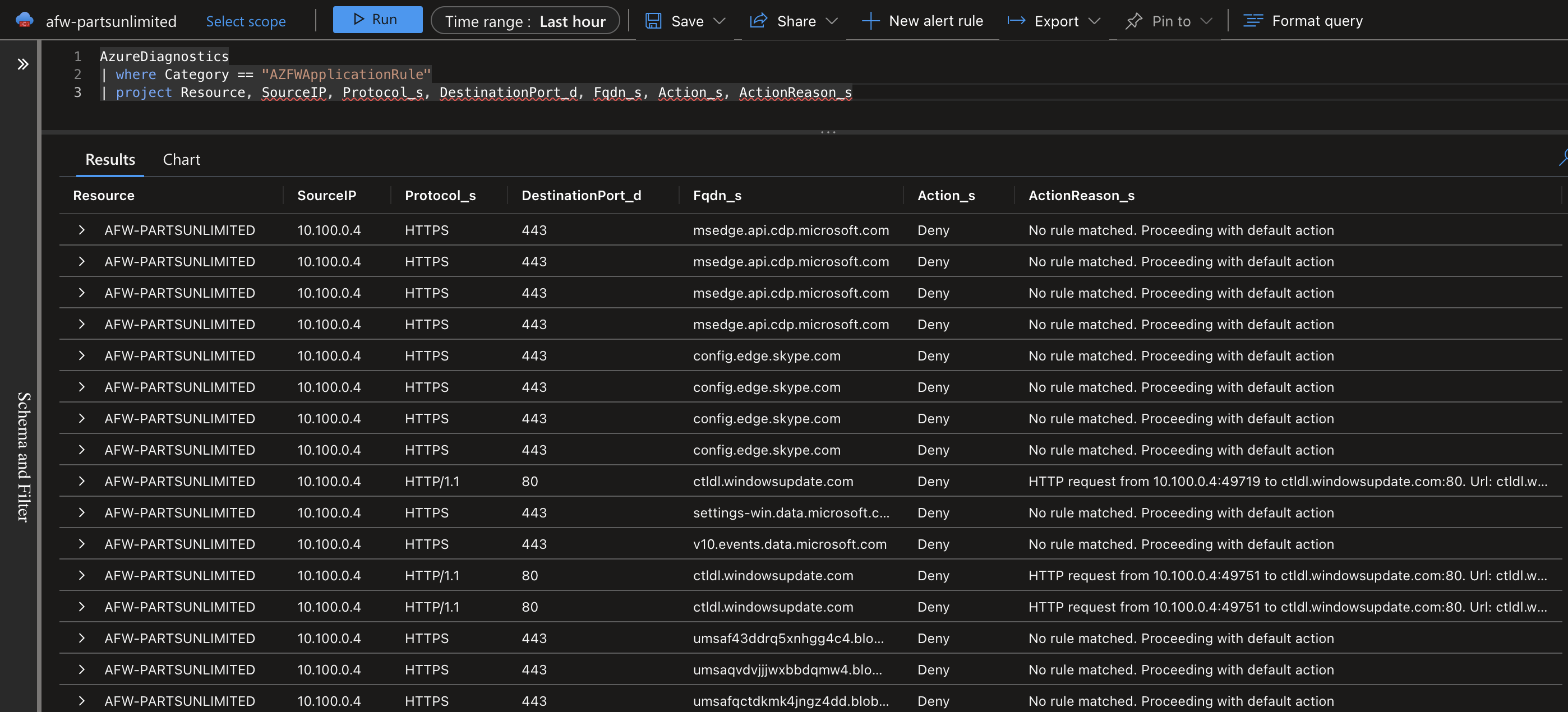
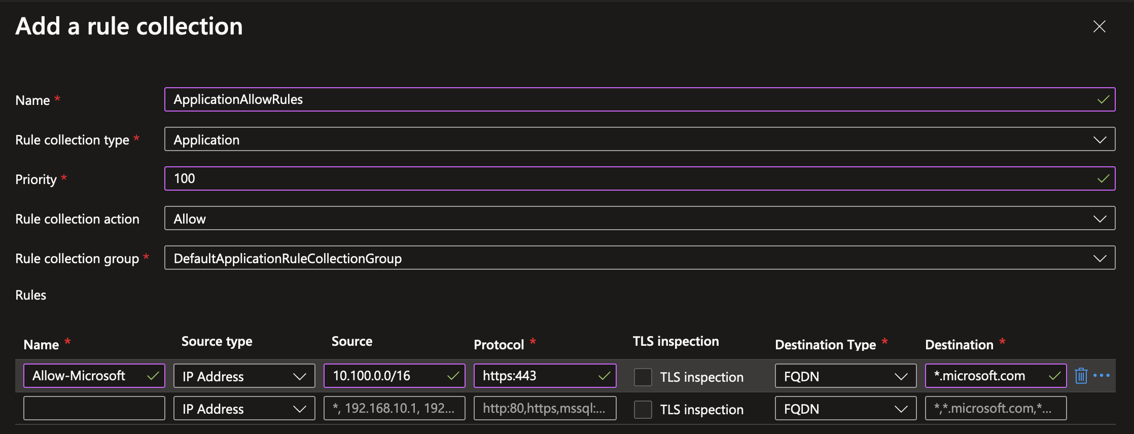
To verify the firewall behavior works as intended, you can easily add a new outbound Application Rule to the Azure Firewall Policy resource which was created when deploying Azure Firewall. For demonstration purposes, I’m adding a very basic rule to allow any traffic from the test spoke VNet which has an IP range of 10.100.0.0/16 to connect to *.microsoft.com over HTTPS. There’s many more options for configuring firewall rules which are an interesting topic for a future blogpost.
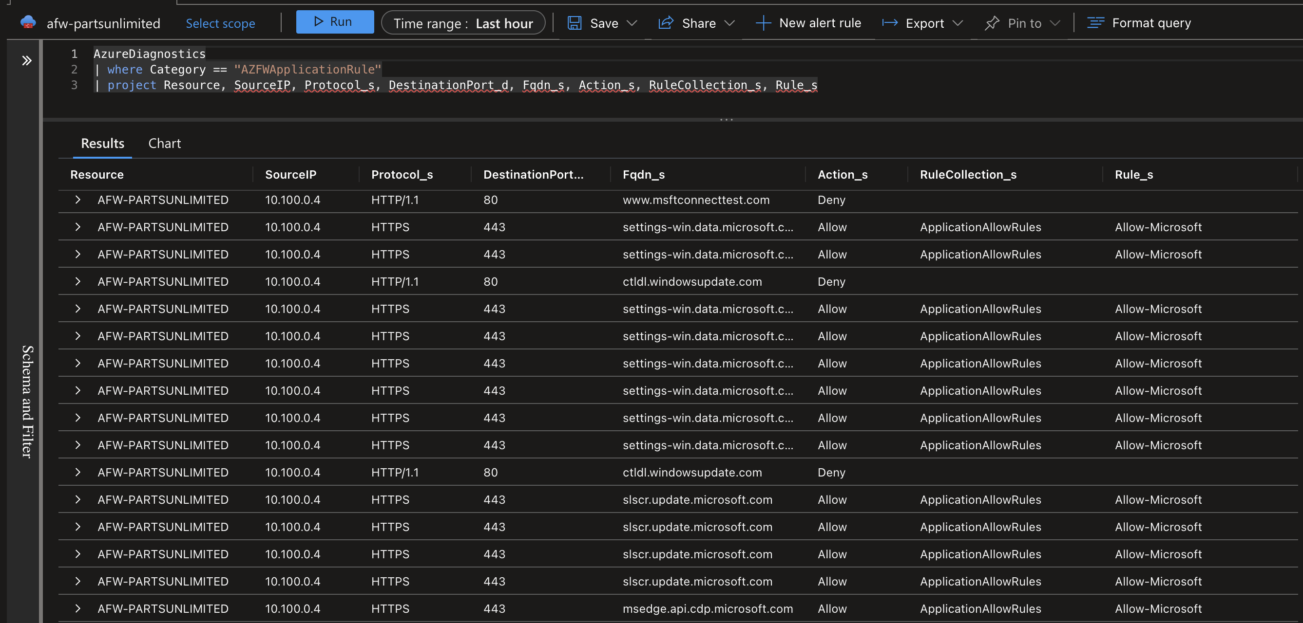
After adding the rule and waiting for a while, the results are visible in the firewall traffic logs. You can see that because I only allowed HTTPS traffic that all HTTP traffic is still denied. Additionally, you can query for which rule (collection) caused the traffic to be allowed or denied, which is a nice feature when your firewall configuration tends to grow in size.
The possibilities for route tables do not end there. Another very common use case is to point traffic destined for other VNets to the Azure Firewall as well, which can then be configured centrally to allow/deny certain types of traffic. There’s many more use cases when using VPN gateways to decide how traffic gets directed to and from your on premises networks.
TL;DR: UDR’s
- Route tables are always present in every VNet containing a set of system default routes.
- Routes in a route table are used to determine where network traffic points towards. These targets are called next hop types.
- User Defined Routes (UDR’s) can be created in a Route Table resource, and are used to override and direct which traffic goes where in your network.
- UDR’s can have multiple next hop types, such as the internet, a VPN gateway or a Network Virtual Appliance (NVA).
- A very common scenario for using UDR’s is to route all VNet-outbound traffic through an NVA like Azure Firewall, which is common in a Hub-Spoke network topology.
Wrapping up
As you’ve seen, there’s loads of tools in the toolbox of a Cloud Engineer. This was just a first step, barely scratching the surface of the possibilities in Azure. For example, this blogpost was focused pretty much on networking within one region. But did you know you can connect everything across Azure regions all around the globe? Or that you can connect your local networks to the Azure backbone using a physical connection with ExpressRoute Direct for the highest speeds and physical network isolation? Got requirements for migrating many terabytes of data to Azure? No worries, you can get a literal data box shipped to your data center where you can load your data on and ship it back to Microsoft.
In this blogpost I’ve focused mostly on deploying resources to subnets, and managing those networks using building blocks like VNet Peering, NSG’s, UDR’s and NVA’s like Azure Firewall. The next step is to make sure traffic from the internet can reach your private network in a secure way. There’s lots of different ways to achieve public internet connectivity in Azure, like Front Door, Application Gateway or even simply opening up your Azure Firewall to allow connectivity with private resources. In a future blogpost I’ll touch upon these and related topics like Azure DNS.
On a more personal note, diving into Azure networking has been a humbling experience and taught me that there’s much, much, much more to learn about running software than I initially imagined. I find it very fascinating to be on border of both Software Development and Cloud Infrastructure, and you can expect many more posts in the future with new learnings and findings!
For now, I hope you’ve learnt something new, even if it’s just conceptually. Thank you for scrolling this far!
Hungry for more?
Comment section
Got any questions or feedback? Leave a comment using GitHub issues!